Contents
-
- <TYPE= “disc”>
Base Code (Version 5.2)
As evident from the name, this version of the code is the core of all the extensions of USM3D. The base version of the code solves the Reynolds-averaged Navier-Stokes equations in their standard form and in a sequential manner (single CPU version for workstations). It is developed with the primary objective of analyzing the compressible flows around complex configurations. The latest export version of this code is version 5.2. Some of the earlier milestone versions of the base code includes version 4.4 (inviscid), and version 5.13 (viscous with multitasking capability on CRAY). The accuracy, robustness and feasibility of the latest version of the code has been accessed by considering a matrix of test cases shown below. Unless stated otherwise, all the computations reported here are based on the implicit time integration scheme.
Test case matrix for the assessment of the base version
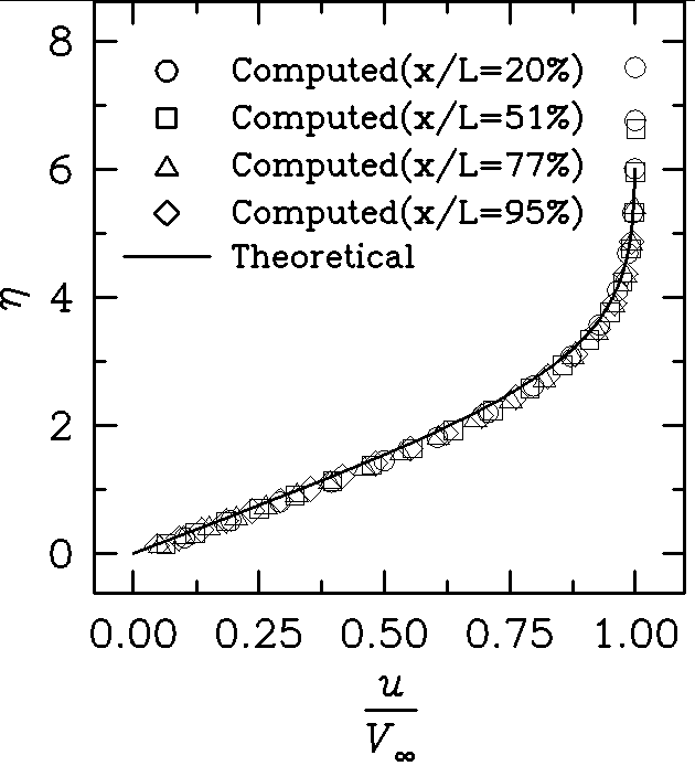
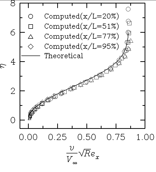
Flat Plate: Laminar Boundary Layer
For this case, an unstructured grid has been generated using a standalone suite of structured-to-unstructured grid generator programs. Initially, an H-topology 49×41 (stream wise x normal) structured grid was constructed that consisted of approximately 16 points across the boundary layer (for a Reynolds number=10,000). Next, the two-dimensional grid was extruded twice in a spanwise direction by a distance of 0.02L to form a three-dimensional dual-channel structured 49x41x3 H-H grid. Finally, from this grid an unstructured tetrahedral grid was constructed by dividing each hexahedral cell in two prismatic cells and further subdividing each of the prismatic cells in three tetrahedra. The unstructured grid consists of 23040 tetrahedral cells and 8384 boundary faces.
The flowfield analysis for this case has been performed considering a parallel moving freestream at a Mach number of 0.5 and a Reynolds number per unit plate length (L) of 10,000. The computations have been performed for 3000 iterations that reduces the flow residue by more than five-and-a-half order of magnitude. Figures 1 and 2 compare the distributions across the boundary layer of the computed tangential velocity and normal velocity respectively, with the corresponding analytical distributions obtained from Blasius solution. The computed solution correctly exhibits the self-similar nature of the flow and compares fairly well with the theoretical solution.
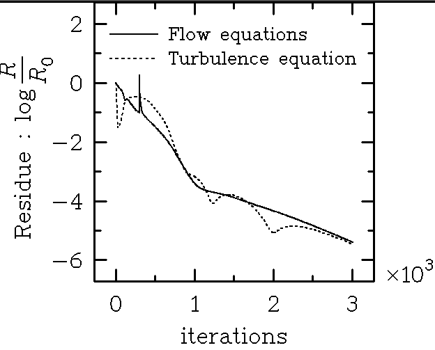
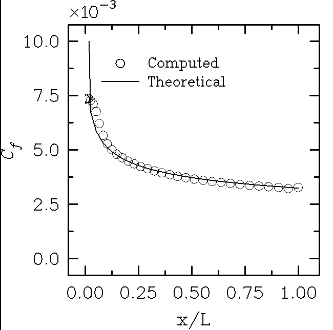
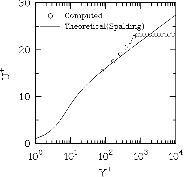
Flat Plate: Turbulent Boundary Layer
The unstructured grid generated for this case is appropriate for the wall function-based turbulent flow analysis. It has all the first nodes off the plate surface positioned at an average Y+ = 80 (for a Reynolds number = 2×10⁶). The grid generation procedure followed here is the same as that described for laminar flat plate case. The unstructured grid is based on the 49x19x3 (stream wise x normal x span wise) dual-channel H-H topology structured grid. It has 8 points (24 tetrahedra) across the boundary layer and consists of 10368 tetrahedral cells and 3984 boundary faces.
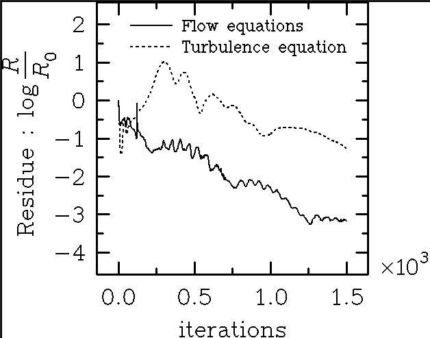
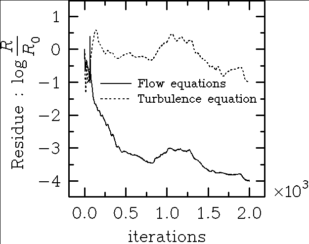
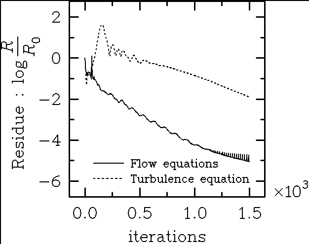
The flowfield analysis for this case has been performed considering a parallel moving freestream at a Mach number of 0.5 and a Reynolds number per unit plate length of 2 million. The computations have been performed for 3000 iterations. At the end of this run, flow residue have been reduced by nearly five-and-a-half order of magnitude. Figure 3 presents the convergence trend of the computations by displaying the history of the flow equations and turbulence model-equation residue. The comparison between the computed and theoretical skin-friction distributions along a flat plate and the law-of-the wall behavior have been presented in Figure 4.
RAE 2822 Airfoil
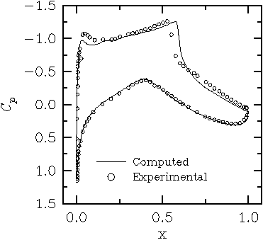
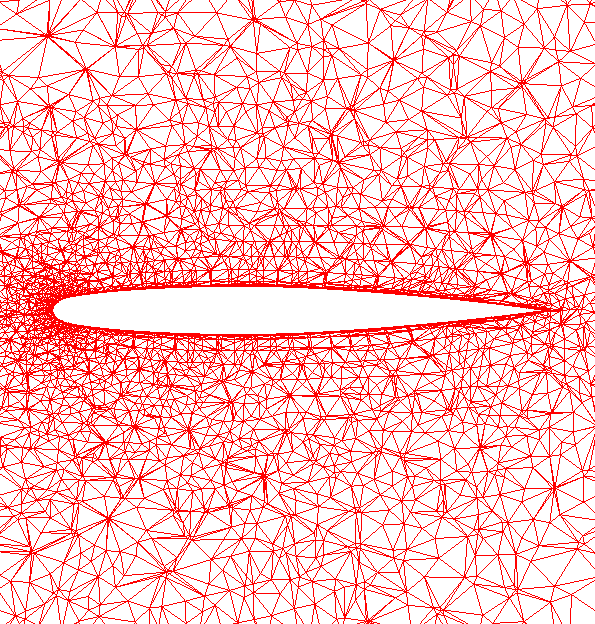
This case has been experimentally tested under the flow conditions that generates a transonic, turbulent, and a shock-induced separated flow environment. The unstructured grid for this case as well as all the following cases has been generated using the grid generator VGRID . In order to apply the production version of the grid generator and the flow solver suitable for only three-dimensional geometries, yet simulate the two-dimensional flow computations, an end-walls mounted rectangular wing made up of RAE 2822 airfoil sections has been generated initially. The grid has been generated with the objective of performing a wall function-based turbulent flow analysis. The nodal spacing of the immediate nodes off the surface has been specified to yield an average Y+ = 50 (for a Reynolds number = 6.2×10⁶). The grid has been anisotropically stretched in the spanwise direction to assess the performance of the flow solver in the presence of high aspect ratio cells, typically encountered for a very complex configuration. The grid has approximately 9 points (27 tetrahedra) across the boundary layer and consists of 48,883 tetrahedral cells and 23,914 boundary faces.
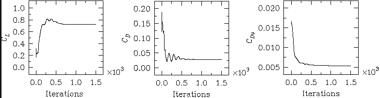
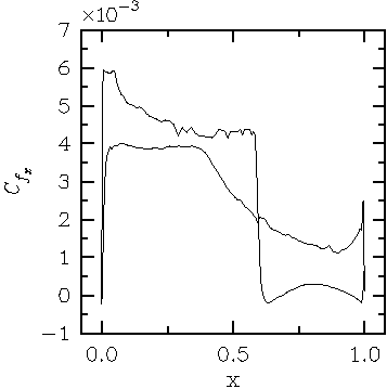
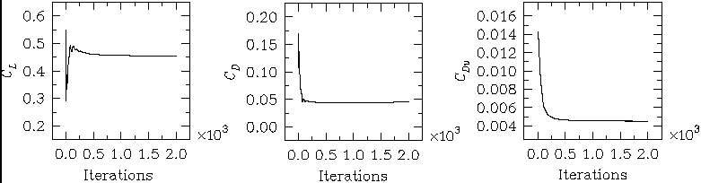
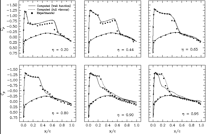
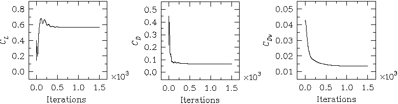
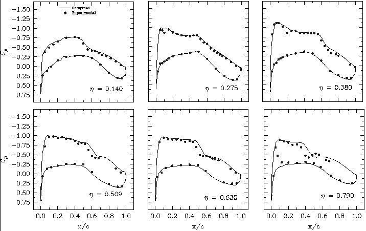
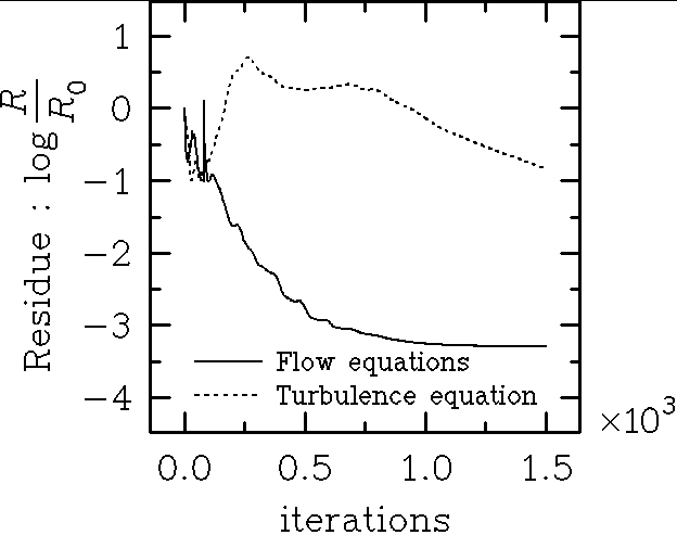
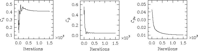
The flowfield analysis for this case has been performed at the experimental conditions corresponding to the freestream flow at a Mach number of 0.75, angle-of-attack of 2.72° and a Reynolds number of 6.2 million based on the unit chord of the airfoil. The flow computations required 1500 iterations to converge. At the end of this run, flow residue have been reduced by more than three order of magnitude. Figures 5 and 6 present the convergence trend of the computations via the history of the governing equations residue and the aerodynamic coefficients, respectively. The comparison between the computed and measured surface pressures has been presented in Figure 7. The computed shock is captured at a location that is aft of the experimentally observed shock location by about <5% of the chord length. The computed streamwise local skin friction distribution is displayed in Figure 8 that shows a small pocket of the shock-induced separated flow.
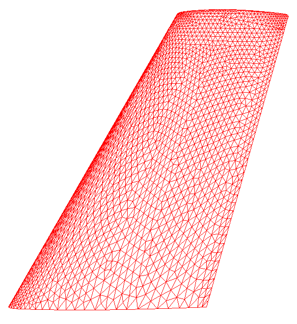
ONERA M6 Wing: Full viscous (grid resolved sublayer) grid
This geometry has been experimentally tested under a high Reynolds number, transonic, separated flow condition. For the present computations, an unstructured grid that fully resolves viscous sublayer has been generated. The spacing of the nodes immediately off the surface has been specified to yield an average Y+ = 1 (for a Reynolds number = 11.7×10⁶ based on the mean aerodynamic chord). The grid has approximately 10 points (30 tetrahedra) across the boundary layer and consists of 495,012 tetrahedral cells and 12,986 boundary faces.
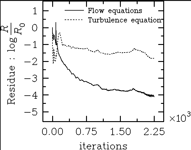
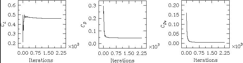
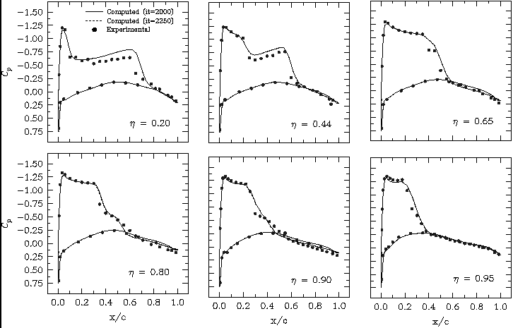
The flowfield analysis for this case has been performed at the experimental conditions corresponding to the freestream flow at a Mach number of 0.8447, angle-of-attack of 5.06° and a Reynolds number of 11.7 million based on the mean aerodynamic chord of the wing. The flow computations have been performed for 2250 iterations. At the end of this run, flow residue have been reduced by more than four order of magnitude. Figures 9 and 10 present the convergence trend of the computations via the history of the governing equations residue and the aerodynamic coefficients, respectively. The comparison between the computed and measured surface pressures has been presented in Figure 11. The computed surface pressure distributions shown at 2000 and 2250 iterations are almost indistinguishable and suggest that the flow has converged within 2000 iterations.
ONERA M6 Wing: Wall function grid
In order to access the suitability of the wall function approach in a separated flow environment, ONERA M6 wing computations have also been performed with the wall function grid. The unstructured grid used for the present computations has been originally generated as a part of the grid sensitivity study by Frink [AIAA Journal, 1998]. The spacing of the nodes immediately off the surface has been specified to yield an average Y+ = 50 (for a Reynolds number = 11.7×10⁶ based on the mean aerodynamic chord). The grid has approximately 4 points (12 tetrahedra) across the boundary layer and consists of 325,017 tetrahedral cells and 10,500 boundary faces. In Figure 12, views of the grid on the wing surface and in a cross-sectional plane have been presented.
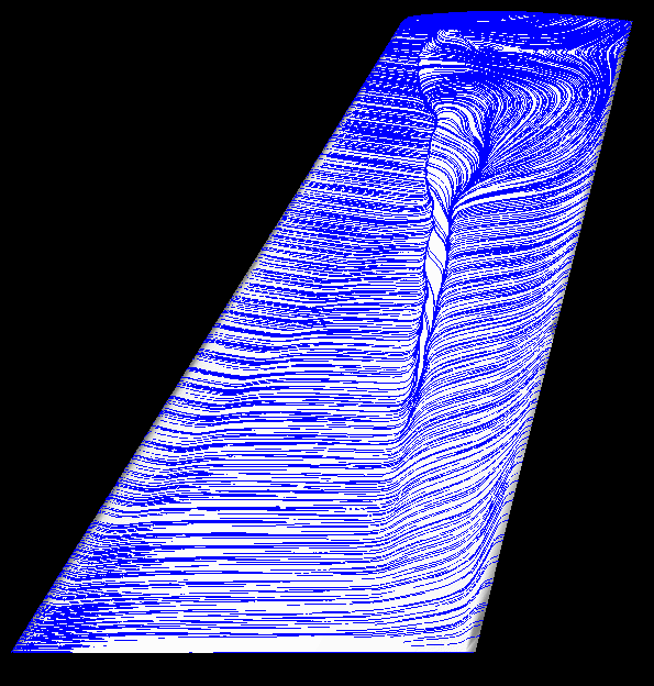
The flowfield analysis for this case has been performed at the experimental conditions corresponding to the freestream flow at a Mach number of 0.8447, angle-of-attack of 5.06° and a Reynolds number of 11.7 million based on the mean aerodynamic chord of the wing. The computed solution has required 2000 iterations to attain convergence. At the end of this run, flow residue have been reduced by more than four order of magnitude. Figures 13 and 14 present the convergence trend of the computations via the history of the governing equations residue and the aerodynamic coefficients, respectively. The computed surface oil-flow pattern is shown in Figure 15 that vividly displays the shock-induced separated flow on the wing surface. The comparison between the computed (present wall function-based solution and the full viscous grid solution) and measured surface pressures has been presented in Figure 16. It is evident from this figure that the wall function-based solution compares well with the full viscous grid-based solution and the experimental results. However, in the wing outboard region where separated flow is present, the wall function-based solution exhibits discrepancy from the full viscous grid-based solution and the measure data. In the wing outboard region, computed shock corresponding to the wall function solution is located upstream of the measured shock, whereas that corresponding to the full viscous grid-based solution displays much better agreement with the measured shock.
(7.5 kb)
NTF PathFinder
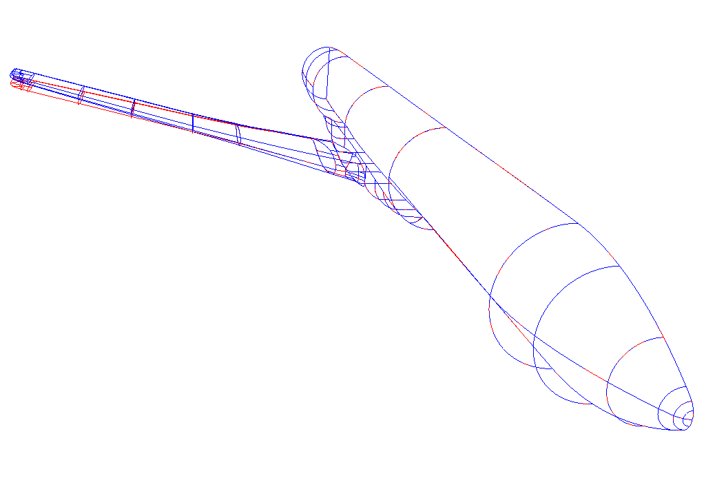
This geometry is a prototype low wing subsonic transport configuration. The geometry has been designated as PathFinder-I lateral controls model which was tested in the National Transonic Facility (NTF). The test had indicated significant aeroelastic deformations of the outboard wing surface of the configuration, although the wing deformations were not measured. This observation has also been computationally confirmed in the study of Cavallo [Masters Thesis, 1995], where it has been shown that incorporating the first order aeroelastic effects in the rigid model provides better agreement with the experimental results, specifically in the wing outboard region. The method performed static aeroelastic computations by coupling the aeroelastic code, ELAPS with a flow analysis procedure demonstrated by Parikh [AIAA Paper 97], which in turn couples inviscid version of USM3Dns (USM44n) with the interactive boundary layer.
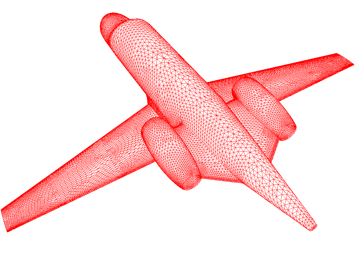
For the present study, the configuration geometry file (.d3m file) is prepared in accordance with the first order aeroelastic deflections computed using the procedure outlined above. The deflected geometry is superimposed on the rigid (before the test) geometry of this configuration as shown in Figure 17 and used as the base configuration for the present study. The unstructured grid generated for this purpose has the spacing of the nodes immediately off the surface specified to yield an average Y+ = 50 (for a Reynolds number = 3×10⁶ based on mean aerodynamic chord). The grid has approximately 6 points (18 tetrahedra) across the boundary layer and consists of 1,222,318 tetrahedral cells and 24,464 boundary faces. Figure 18 presents a view of the grid on the configuration surface.
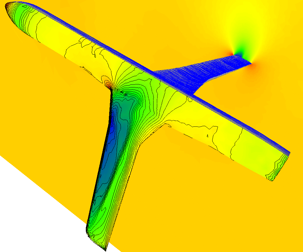
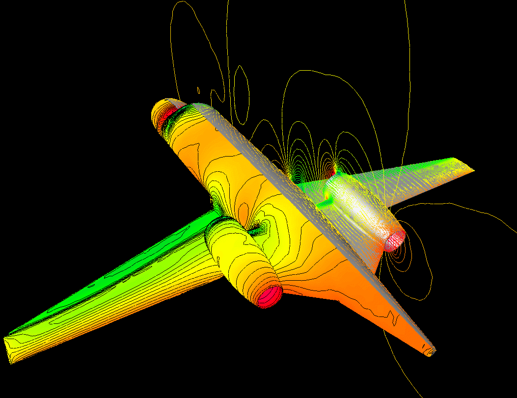
The flowfield analysis for this case has been performed at the experimental conditions corresponding to the freestream flow at a Mach number of 0.81990, angle-of-attack of 1.9822° and a Reynolds number of 3.0 million based on the mean aerodynamic chord of the wing. The flow computations have been performed for 1500 iterations. At the end of this run, flow residue have been reduced by more than five order of magnitude. Figures 19 and 20 present the convergence trend of the computations via the history of the governing equations residue and the aerodynamic coefficients, respectively. The computed pressure contours on the body surface and a cross-sectional plane passing through the wing as well as the computed surface oil-flow patterns are shown in Figure 21. Whereas, the comparison between the computed and measured surface pressures has been presented in Figure 22.
While the computations are in fairly good agreement with the corresponding measured values, it is noted that the computed shock on the wing outboard is somewhat aft of the experimental shock. It should be noted that the method for computing deflected shape is only suitable for considering the first order aeroelastic effects. Moreover, the flow analysis component used for the integrated procedure of Cavallo is based on the interactive boundary layer method coupled with the inviscid flow calculations. The main reason being that the fully validated viscous grid movement method was not developed. Once it is developed and validated, substituting the previously used flow analysis procedure with the full Navier-Stokes equations based flow analysis capability may improve the accuracy of the configuration prediction shape and consequently the flow computations prediction.
Generic Business Jet
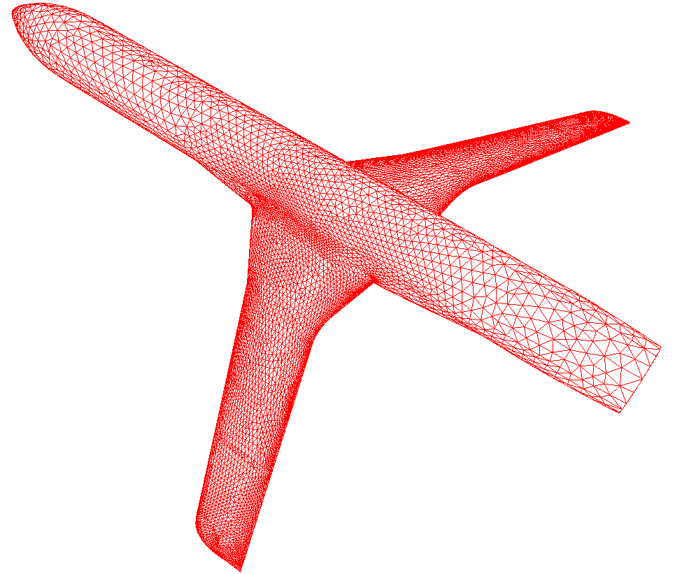
This configuration has a pylon and nacelle mounted on the fuselage. For this generic configuration, experimental results are not available. The present computations have been performed to just explore the feasibility of the flow solver for a more complex geometry than the ones studied previously. The present computations simulate the flow-through engine. However, the flow solver has also an engine-simulation capability available through engine boundary conditions to mimic the engine effects on the surrounding flowfield. This capability will be demonstrated on the same configuration in future.
The unstructured grid for this case has been generated with an objective to apply a wall-function capability of the flow code. Accordingly, the spacing of the nodes immediately off the surface has been specified to yield an average Y+ = 50 (for a Reynolds number = 10 7 based on root chord). The grid has approximately 8 points (24 tetrahedra) across the boundary layer and consists of 1,610,507 tetrahedral cells and 40,732 boundary faces. A view of the surface grid is present in Figure 23.
The flowfield analysis for this case has been performed at the conditions corresponding to the freestream flow at a Mach number of 0.75, angle-of-attack of 3.0° and a Reynolds number of 10 million based on the wing root chord. The flow computations required 1500 iterations to converge. At the end of this run, flow residue have been reduced by more than three order of magnitude. Figures 24 and 25 present the convergence trend of the computations via the history of the governing equations residue and the aerodynamic coefficients, respectively.
The computed pressure contours on the body surface and a cross-sectional plane passing through the nacelle as well as the computed surface oil-flow patterns are shown in Figure 26.
Parallel Code (Version 5.13)
The flow solver USM3Dns has been parallelized for efficient operation on both shared memory systems and a cluster of UNIX workstations connected by a local area network. A single-block, tetrahedral, unstructured grid is efficiently partitioned into a user specified number of contiguous partitions each containing nearly equal number of grid cells. Grid partitioning is accomplished by a mathematically rigorous “spectral bifurcation” graph partitioning technique called Metis with suitable modifications for its applicability to the TetrUSS system.
Communication between partitions is accomplished by suitably embedded Message Passing Interface(MPI) calls into the solver. The flow solver has been made efficient with innovative use of specialized data structures, send and receive arrays, and “cache friendly” local renumbering of cells in a partition. Nearly linear or super linear performance has been demonstrated by use of “non-blocking” communication techniques, where
appropriate.
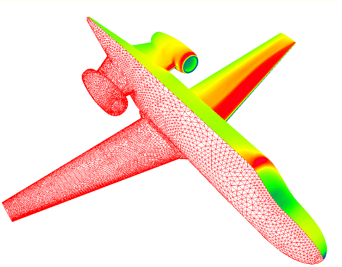
The efficiency of the parallel version of USM3Dns is demonstrated on a generic business jet configuration, comprising of a fuselage, a wing and an engine nacelle mounted on the rear of the fuselage. A viscous grid suitable for wall functions formulation(Y+=50) was generated on this configuration and consisted of 1,610,507 tetrahedral cells and 280,904 grid points. Figure 1 shows the triangular surface grid and a typical surface pressure plot.
The parallel flow solver was run on an increasingly larger number of processors for 1500 iterations each, and cpu time per iteration was monitored. The size of the grid did not permit operation on less than 10 processors. Figure 2 shows the speed-up obtained versus the number of processors, assuming that a 10-processor solution gave a speed-up of 10 as compared to a single processor solution.
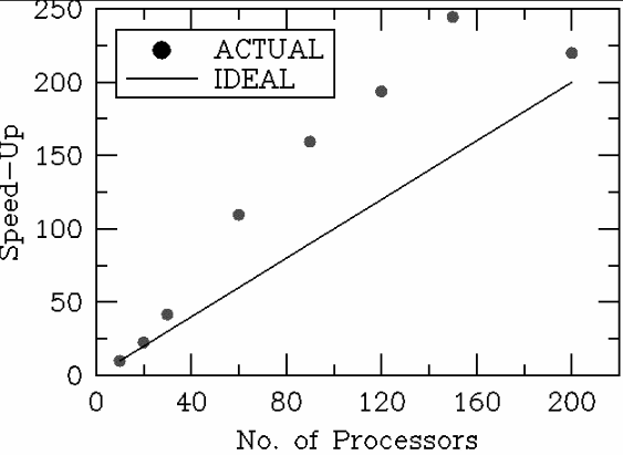
The observed Speed-up has been compared with its ideal performance, which is linear (meaning that a job run on a “n” processor machine is “n” times as fast as on a single processor machine). The more than ideal (or super-linear) performance is believed to be due to increased “cache” efficiency of the parallel solver as compared to a single processor. It should be noted that in unstructured grids, widely different array indices are required in computations. This requires indiscriminate use of the computer cache memory, resulting in a large number of cache misses and hence the wall clock time per iteration becomes cache dominated. As the grid size per partition becomes smaller with increasing number of processors, the cache hits per iteration are reduced, thus making the parallel very efficient. However, for a given grid size there is a finite number of partitions beyond which the communication time between partitions becomes larger than the computational time, and the efficiency eventually falls off. It may be noted that the final results were same on any number of processors, attesting to the accuracy of the code in parallel mode.
Newly Added Boundary Conditions
Propeller/Rotor Boundary Condition
This boundary condition facilitates simulation of propeller effects
on the flowfield. The boundary condition models a propeller as an actuator
disc. In the present implementation, the propeller is represented as
two distinct zero-thickness surfaces collapsed on each other. A special
procedure that generates grids around zero-thickness surfaces based on VGRIDns has to be used for this boundary condition. The flow solver input
for this case includes specification of rotor geometry, thrust, torque and flag governing the type of simulation (uniform or radially varying jump
conditions across the rotor). The grid generation procedure and propeller-specific input parameters have been illustrated in Chapter 3: BOUNDARY CONDITIONS FOR USM3Dns
This boundary condition has been demonstrated by considering a
hypothetical configuration that includes ONERA M6 wing and a propeller.
The propeller radius of 0.2*wing-span has been considered and it has been
positioned at the wing tip in front of the leading edge. The viscous
unstructured grid has been generated using the special procedure for grid
generation mentioned above. The grid consists of 798,204 tetrahedral cells
and 17,408 boundary faces. For this case, radial variations of pressure
and swirl jump across the propeller have been prescribed.
The flowfield analysis for this case has been performed by considering
a freestream flow at Mach number of 0.60, angle-of-attack of
5.06° and a Reynolds number of 15.1 million per unit length.
Radial variations of pressure and swirl jump across the propeller have
been prescribed. Two flow computations have been performed by considering
clockwise and counterclockwise direction for propeller rotation but with
the identical thrust and torque levels. Additionally, a baseline solution
has been generated by considering the ONERA M6 wing without propeller. The
convergence history for all the runs has been presented in the Figure 1
below. A propeller rotating in a clockwise and counterclockwise directions
produces a downwah and an upwash respectively, on the wing. This effect is
evident in the increased lift for the case with a counterclockwise rotation
of the propeller. Figure 2 below shows a comparison of surface pressure
coefficient distributions at two cross-sections of the wing. The propeller
has been located at the wing tip and therefore it has more pronounced
effects on the flow at the outboard section. The propeller thrust and
torque effects have been shown in Figure 3 via pressure distribution
and swirl on the aft surface of the propeller. The figure also shows wing
surface flow pattern that indicates flow separation on the wing
outboard for the counterclockwise rotation of the propeller.
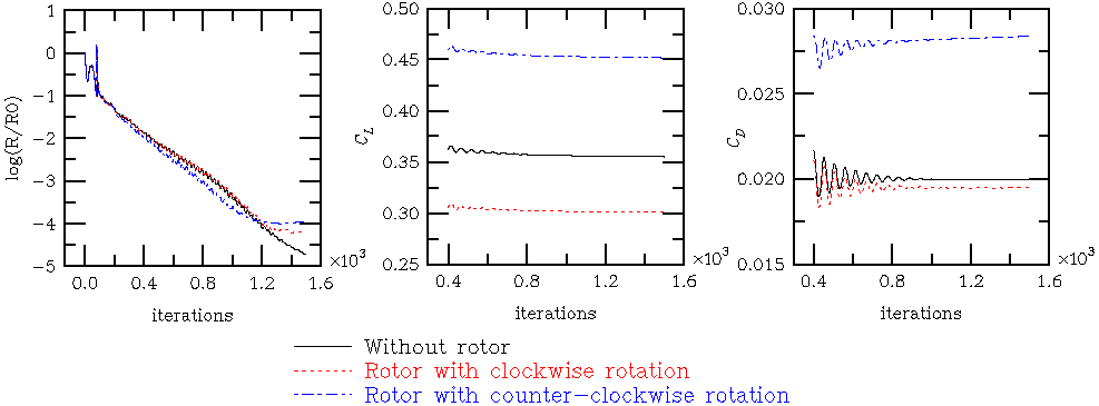
Fig. 1: Convergence history for ONERA M6 wing with and without propeller
(9.3kb)
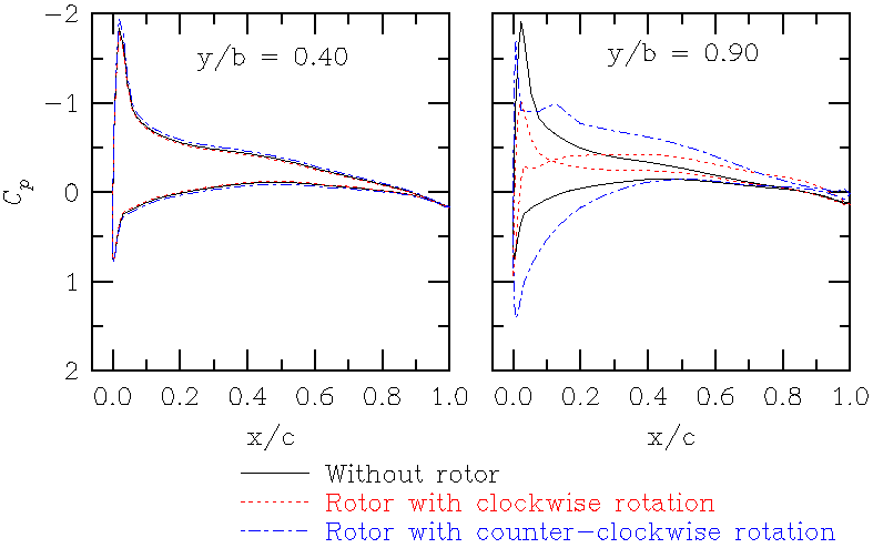
Fig. 2: Comparison of the computed surface pressure coefficient distributions for ONERA M6 wing with and without propeller
(10.07kb)
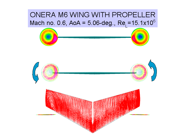
Fig. 3: Comparison of the rotor pressure, swirl and
wing surface flow pattern for two differnt directions of a propeller rotation
(49.5kb)
