Example Files
Summary of available boundary conditions
| B.C. Flags | Description | Application |
|---|---|---|
| 0 | Freestream | Supersonic Inflow |
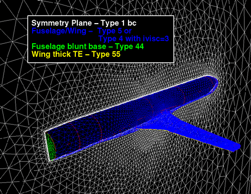
| 1 | Tangent Flow | Reflection plane |
| 2 | Full Extrapolation | Supersonic Outflow |
| 3 | Characteristic Inflow/Outflow | Subsonic Outer Boundaries |
| 4 | No-Slip | Viscous Surfaces |
| 5 | Tangent Flow | Inviscid aerodynamic surface |
| 41 | Special no-slip | Moving viscous surfaces |
| 44 | Special no-slip | Blunt base |
| 55 | Special “Wake” B.C. | Thick Trailing Edges |
| 1001 | Special inflow | Inflow to internal flow problems |
| 1002 | Special outflow (fixed pressure) | Outflow plane for internal flow problems |
| 10101 | Engine intake | Engine inflow plane |
| 10102 | Engine exhaust (jet core) | Jet-core outflow from Jet or Turbofan Engine |
| 10111 | Sink | Sink |
| 11002 | Special outflow (fixed pressure) | Outflow plane for internal flow problems |
| 11003 | Special outflow (fixed Mach) | Outflow plane for internal flow problems |
B.C. Flag – 0
Purpose:
Enforces freestream flow on an inflow boundary.
Use:
Most commonly used for supersonic inflow boundaries.
How it works:
Sets (rho, u, v, w, pressure) across boundary face based on the Mach
number, alpha, and beta prescribed in the input file.
B.C. Flag – 1
Purpose:
Enforces a tangent flow condition. Has some special treatments of nodal
values to insure tangency on a symmetry plane.
Uses:
-
- Symmetry planes
- Inviscid wind-tunnel walls
- Inviscid stings supporting a viscous aircraft configuration
- Inviscid surfaces which user does not want to be included in global force & moment integration which will pick up type 4, 5, 41, 44, and 55 b.c.’s
How it works:
-
- Velocity components u, v, and w are extrapolated to boundary surface via. Taylor series expansion. The normal component is subtracted from the vector, leaving the tangent component.
- There is a special treatment of nodal-averaged quantities to insure no leakage in corners intersecting a symmetry plane.
- Type 1 b.c. is not included in the global force & moment integration.
B.C. Flag – 2
Purpose:
Supersonic outflow boundary
Uses:
Most often used for downstream far-field boundary for supersonic flow
calculation.
How it works:
Extrapolates (density, u, v, w, pressure) from interior domain cell
to the outflow boundary using a Taylor series expansion.
Special Note:
When setting up a supersonic, external flow problem with a “box” outer
boundary planes, be sure to:
-
- Set type 0 on inflow plane
- Set type 3 on top, side, and bottom planes (if normal velocity component is subsonic)
- Set type 2 on outflow plane (assuming normal velocity component is supersonic)
It is important to use type 3 on top, side, and bottom planes if the normal Mach number is subsonic.
B.C. Flag – 3
Purpose:
Characteristic inflow/outflow b.c.
Uses:
-
- Far-field boundaries for subsonic/transonic external flow problems.
- Top, side, and bottom planes of far-field “box” boundary of external supersonic flow problem when normal velocity component is subsonic.
How it works:
Uses the fixed and extrapolated Riemann invariants corresponding to
the incoming and outgoing waves traveling in characteristic directions
defined normal to the boundary. The invariants are used to determine the
locally normal velocity component and speed of sound. The density is computed from the entropy relation, and the pressure from the ideal gas law using the square of the speed of sound.
B.C. Flag – 4
Purpose:
Viscous surface b.c.
Uses:
How it works:
-
- If ivisc=1 or 2, a no-slip condition is applied to boundary surface,
i.e. u=v=w=0.- For ivisc=1, assumes laminar flow
- For ivisc=2, assumes turbulent flow using Spalart-Allmaras turbulence model integrated to the wall
- If ivisc=3 in input file, turbulent flow is assumed and a wall function
is applied to viscous surface. Wall function is applied to first cell on surface, and produces a slip velocity. Cells above the first cell are solved numerically with the Spalart turbulence model.- Not currently available in USM3D-ME
- Type 4 b.c. is included in the global force and moment integration.
- If ivisc=1 or 2, a no-slip condition is applied to boundary surface,
B.C. Flag – 5
Purpose:
Inviscid surface b.c.
Uses:
Used for inviscid aerodynamic surfaces which user wants included in
the global force & moment integration. Most commonly used for aircraft
surface when inviscid flow is assumed (ivisc=0).
How it works:
-
- Velocity components u, v, and w are extrapolated to boundary surface via. Taylor series expansion. The contravariant component is subtracted from the vector, leaving the tangent component.
- Type 5 b.c. is included in the global force and moment integration.
B.C. Flag – 41
Purpose:
Special no-slip b.c., i.e. u=v=w=0
Uses:
Moving viscous surface with ivisc = 1 or 2.
How it works:
Applies no-slip (u=v=w=0) on surface(s) translating at speed xmach.
B.C. Flag – 44
Purpose:
Special no-slip b.c., i.e. u=v=w=0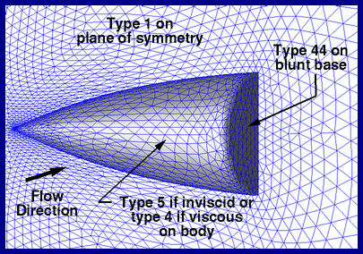
Uses:
Blunt bases when upstream b.c. is either inviscid (type 5, ivisc=0)
or viscous with wall function (type 4, ivisc=3)
How it works:
The type 5 and type 4 with wall function both have finite tangent-flow
velocities on the aerodynamic surface. With a blunt base present, a singularity
is created at the sharp corner. Often the flow will experience a numerically
induced flow separation at the corner which relieves the singularity, but
sometimes the flow will try to expand to negative pressure.
The type 44 b.c. sets a zero-velocity on the blunt base and on the nodes
along the corner. This tends to force the flow separation and creates a
more stable numerical solution. The assumption is that the real viscous
flow would do this anyway.
If type 4 b.c. is used without wall function on upstream aerodynamic surface, i.e. ivisc=1 or 2, then the type 4 and 44 are identical.
The type 44 b.c. does get picked up in the global force & moment integration.
Note the types 4 and 44 are identical in USM3D-ME since wall functions are currently not available.
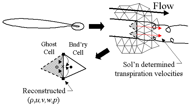
B.C. Flag – 55
Purpose:
To mimic a “wake-like flow” leaving a finite-thick trailing edge (TE).
It is presently difficult to “grid resolve” the wake region behind an
aerodynamic surface using thin-layered tetrahedra. The type 55 b.c. serves
as an artifice to facilitate the flow leaving the trailing edge smoothly
rather than trying to turn across the corner singularity.
As illustrated below, set the thick TE patches to type 55 when the it
is connected to an upstream patch having a finite surface velocity, i.e.
for inviscid flow, type 5, or viscous flow with wall function, type 4 with
ivisc=3.
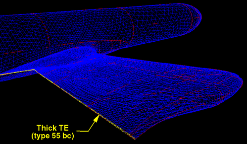
Uses:
The type 55 b.c. is most often used for thick trailing edges (TE’s)
which are not adequately resolved by thin layers of tetrahedra in the wake
region.
Use this b.c. for any thick TE surface, e.g. wing TE, nacelle cowl TE,
fin TE, etc.
How it works:
The type 55 b.c. averages the reconstructed primitive variables from
the nodes to the boundary face and ghost cell. This results in a solution
determined transpiration velocity emanating from the finite thick TE
that alleviates the corner singularity. The result is a smooth departure
of the upper/lower surface flow from the TE in a manner similar to wake
being present.
This b.c. has been well tested and is used extensively.
B.C. Flag – 1001
Purpose:
Special 2D inflow b.c. for some internal flow problems.
Uses:
Developed for flat-plate boundary layer calculations on 2D “channel”
grids.
Can be used for inflow condition for a “wind-tunnel” grid.
How it works:
Enforces constant freestream entropy, total pressure, and v=0. Extrapolates q^2 = u*u + w*w from downstream to determine static pressure on boundary.
B.C. Flag – 1002
Purpose:
Special subsonic outflow b.c.
Uses:
Used for flat-plate boundary layer calculations on 2D “channel” grids.
Can be used for outflow condition for a “wind-tunnel” grid.
How it works:
Extrapolates density, u, v, w, and sets back-pressure to constant level prescribed by input parameter “pbc1002“.
Note that a freestream value of back-pressure would be p_bc1002 = 1/gamma = 0.714285
B.C. Flag – 10101, 10102
Purpose:
To simulate jet or jet-engine exhaust flow effects on aggregate configuration
aerodynamics.
Uses:
This b.c. is used to simulate the jet engine configurations illustrated
below. The boundary conditions for the various patches should be set accordingly. The grid only extends to the inlet and exit plane boundaries.
The grey hatched region is not included in the grid.

How it works:
The jet outflow boundary condition is determined from user-prescribed
values for total pressure, p0jet, and total temperature, T0jet,
conditions assumed “inside” the engine. The “inside” region contains no
grid, but is used as a black-box for setting engine parameters according
to model described in:
Hartwich, P. M. and Frink, N. T.: “Estimation of Propulsion Effects
on Transonic Flows Over a Hypersonic Configuration”, AIAA Paper 92-0523,
January 6-9, 1992.
The inlet-plane flow is determined automatically in USM3Dns through a mass flux balance with the jet and fan flows by adjusting an average back pressure on the face. By using an average back pressure, the distortion on the inflow plane is maintained while the mass flux is balanced.
How to set engine parameters:
- Define dimensional values for total temperature (Ttotal_jet, deg Rankine)
and total pressure (Ptotal_jet, psia) for the engine. Also provide dimensional
values for freestream pressure (P_infinity, psia) and temperature (T_infinity). - Each 10101 and/or 10102 patch requires the addition of a line at the end of the proj_name.patchdata file. Examples are provided below for the three cases shown in the above image.
- Jet Alone:
- core_patch# 10102 9 fuel gammaj pjet p0jet Rratio T0jet vec(1) vec(2) vec(3)
- Turbojet:
- core_patch# 10102 9 fuel gammaj pjet p0jet Rratio T0jet vec(1) vec(2) vec(3)
- patch# 10101 1 core_patch#
- Turbofan:
- core_patch# 10102 9 fuel gammaj pjet p0jet Rratio T0jet vec(1) vec(2) vec(3)
- bypass_patch# 10102 9 fuel gammaj pfan p0fan Rratio T0fan vec(1) vec(2) vec(3)
- patch# 10101 2 core_patch# bypass_patch#
- Jet Alone:
Parameters are defined as:
fuel = mass fraction of fuel relative to total exhaust mass flow
gammaj = ratio of specific heats for jet or fan
pjet = static nozzle pressure (usually set to freestream nondimensional pressure = 0.7143)
p0jet = (Ptotal_jet / P_infinity) * 0.7143
Rratio = (spec. gas constant of air) / (spec. gas constantof jet)
T0jet = Ttotal_jet / T_infinity
vec(1) = x-direction cosine of jet or fan flow vector
vec(2) = y-direction cosine of jet or fan flow vector
vec(3) = z-direction cosine of jet or fan flow vector
Notes regarding 10101 and 10102 b.c. types:
- For the current implementation, the inflow boundary flow is automatically balanced with the outflow mass flux. Future versions of USM3Dns may allow the user to set up an inlet-alone case and prescribe a mass flux.
- Be sure to set the engine inflow and outflow b.c.’s as shown above in the project.mapbc file.
- As shown in the sketches, it is desirable to inset the inflow and exit planes from the ends of the nacelle so that some tetrahedral grid extends into the engine nacelle.
B.C. Flag – 10111
Purpose:
Sink b.c.
Uses:
How it works:
B.C. Flag – 11002
Purpose:
Special subsonic outflow b.c.
Uses:
The type 11002 b.c. is similar to the type 1002 b.c. The type 1002 b.c. only allows the user to specify a single value of back pressure for all 1002 type patches. With the type 11002 b.c., the user can prescribe unique back pressure values to all 11002 patches, if desired.
How it works:
Extrapolates density, u, v, w, and sets back-pressure to constant level prescribed in proj_name.patchdata file. To invoke the 11002 b.c., the following line should be added to the end of proj_name.patchdata file for each type 11002 patches in the proj_name.mapbc file.
patch# 11002 1 p_nondim
The patch# input should correspond to the boundary number defined in the proj_name.mapbc file and p_nondim = p/gamma/pinf = p*0.714285. Note that a freestream value of back-pressure would be p_nondim = 1/gamma = 0.714285.
B.C. Flag – 11003
Purpose:
Special subsonic outflow b.c.
Uses:
The type 11002 b.c. is similar to the type 1002 b.c. The type 1002 b.c. only allows the user to specify a single value of back pressure for all 1002 type patches. With the type 11002 b.c., the user can prescribe unique back pressure values to all 11002 patches, if desired.
How it works:
Extrapolates density, u, v, w, and sets back-pressure to constant level prescribed in proj_name.patchdata file. To invoke the 11002 b.c., the following line should be added to the end of proj_name.patchdata file for each type 11002 patches in the proj_name.mapbc file.
patch# 11002 1 p_nondim
The patch# input should correspond to the boundary number defined in the proj_name.mapbc file and p_nondim = p/gamma/pinf = p*0.714285. Note that a freestream value of back-pressure would be p_nondim = 1/gamma = 0.714285.