Salient features of USM3D (Legacy)
- Full Navier-Stokes: includes all cross terms
- Thermodynamic models
- perfect gas for AIR
- Parallel processing
- Parallel execution on multiple CPUs using decomposed zonal grid
- Message passing through MPI
- Time integrations
- Steady State (Implicit Point Gauss-Seidel & Explicit Runge-Kutta)
- 2nd Order Time Stepping
- Newton time stepping
- Dual time stepping
- Upwind flux functions
- Roe’s Flux Difference Splitting (FDS)
- Van Leer’s Flux Vector Splitting (FVS)
- AUSM scheme
- HLLC scheme
- LDFSS Scheme
- MinMod and Superbee flux limiters and Eigenvalue limiter
- Turbulence Models
- Spalart-Allmaras (SA) turbulence model
- SA with Detached Eddy Simulation (SADES)
- Menter Shear-Stress Transport (SST)
- k-epsilon model
-
- Girimaji nonlinear shear stress
- Shi/Zu/Lumley nonlinear modelAlgebraic Reynolds Stress Model (ARSM)
- Transition tripping at prescribed locations
- Overset Chimera grids (static and dynamic)*
- integrated with DiRTlib by Dr. Ralph Noack, Univ. Alabama at Birmingham
- CDISC design within extracted sub-grid zones
- Grid motion
- Solid-body or deforming grid motion
- Special sinusoidal oscillation
- Coupled with external motion controller
- 6-Degree of Freedom (6DOF) capability*
- Coupled with AEDC FDCADRE* and SixDOF controller by Dr. Greg Power, AEDC
- Trajectory integration
- Store/stage separation
- Boundary conditions
- Freestream inflow
- Symmetry
- Supersonic outflow
- Characteristic inflow/outflow
- Solid no-slip wall
- Solid turbulent wall function
- Solid tangency wall
- Zonal boundary interface condition
- Double-fringe overlapping tetrahedral grids
- Periodic boundaries
- Trailing-edge wake simulation
- Propulsion systems
- inlet with prescribed mass flow and swirl
- jet exhaust with swirl
- coupled jet exhaust with inlet
- Actuator-disc propellor model with radial load variation
- Portable (Linux clusters, SGI, HP, IBM, Mac)
- * Requires 3rd party software request
Convention used for coordinate system in USM3D
It is important to construct the computational grid in the correct coordinate system in order for alpha, beta, and the force & moments to be interpreted correctly.
The required coordinate system is:
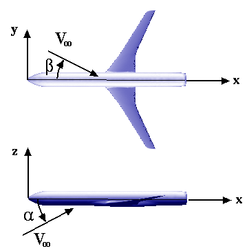
- x – longitudinal body axis (positive in downstream direction)
- y – spanwise or lateral body axis (positive to pilot’s right if computing
lateral/directional coefficients on full configuration. Otherwise the y-direction is not important.) - z – vertical direction in body axis (positive upward)
Force & Moment sign conventions:
- Alpha (x-z plane) – Positive nose up
- Beta (y-z plane) – Positive for yaw to the left
- Pitching moment (x-z plane) – Positive pitch up
- Rolling moment (y-z plane) – Positive roll right
- Yawing moment (x-y plane) – Positive yaw right
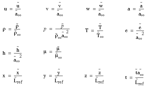
Nondimensionalization used in USM3D
The flow solver employs following scheme for the nondimensionalization of various parameters of interest.
Considering the convention used for the coordinate system in USM3D and the nondimensionalization scheme described above, the freestream and other relevant quantities assume the following nondimensional values/form.
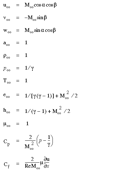
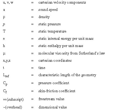
where:
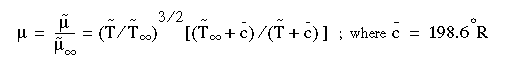
Sutherland’s law for the molecular viscosity mentioned above is given by: